Replacing a ripped-off LED on a DEF CON 34 badge
The bottom LED on my DEF CON 34 badge got ripped off the board. The LEDs form a chain, so with the bottom removed, only three of the eight LEDs work. As a challenge to myself, I replaced the LED.
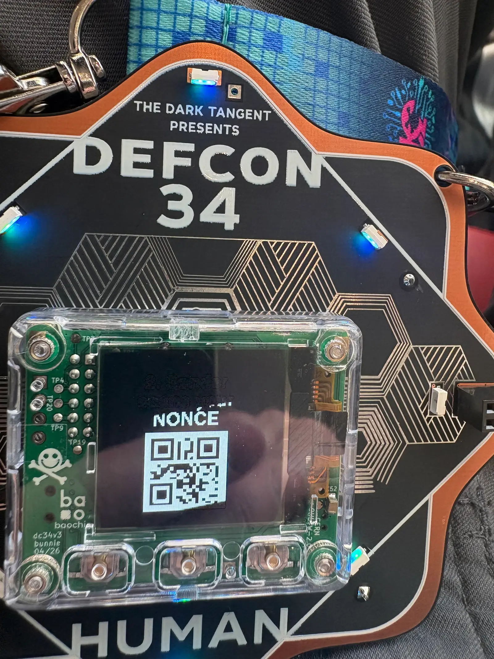
Here is the original badge. LEDs form a ring around the outside and point towards the middle.
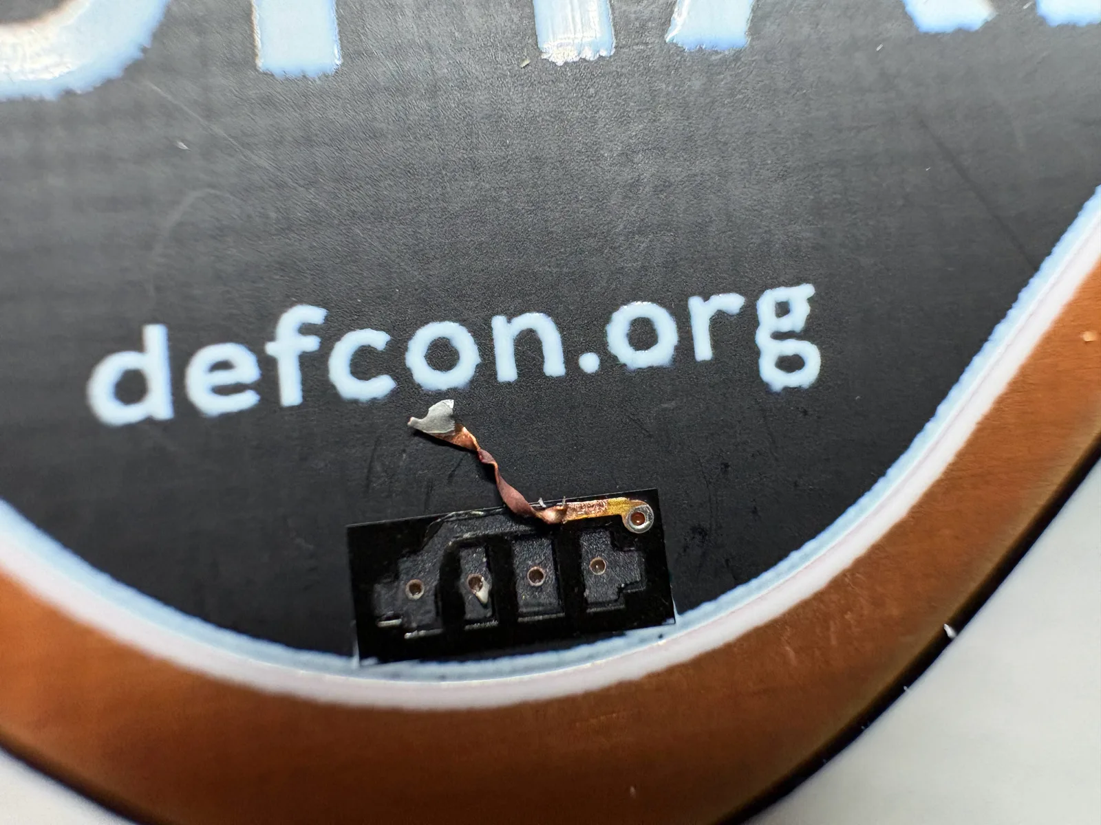
The damage
The rip removed all four pads. This makes repair significantly more challenging. The vias remain and are still good. The upper right via connected to the dangling pad is a redundant ground.
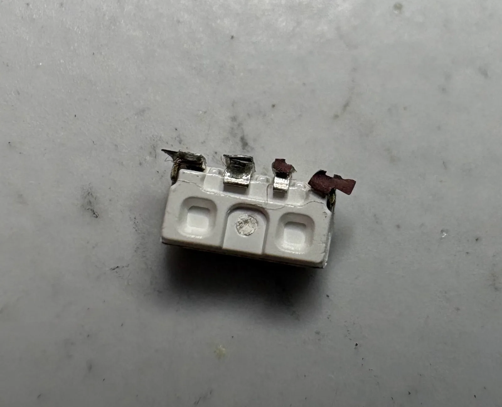
Here is the damaged LED that came off. It might still work, but I've never soldered anything this small before so I decided to order a bunch so it wouldn't matter if I destroyed a few.
Parts
Thankfully, the badge schematic is available: dc34-human-v3-binv. It identifies the part number of the LEDs as SK6812SIDE-A-RVS.
I ordered them from LCSC Electronics.
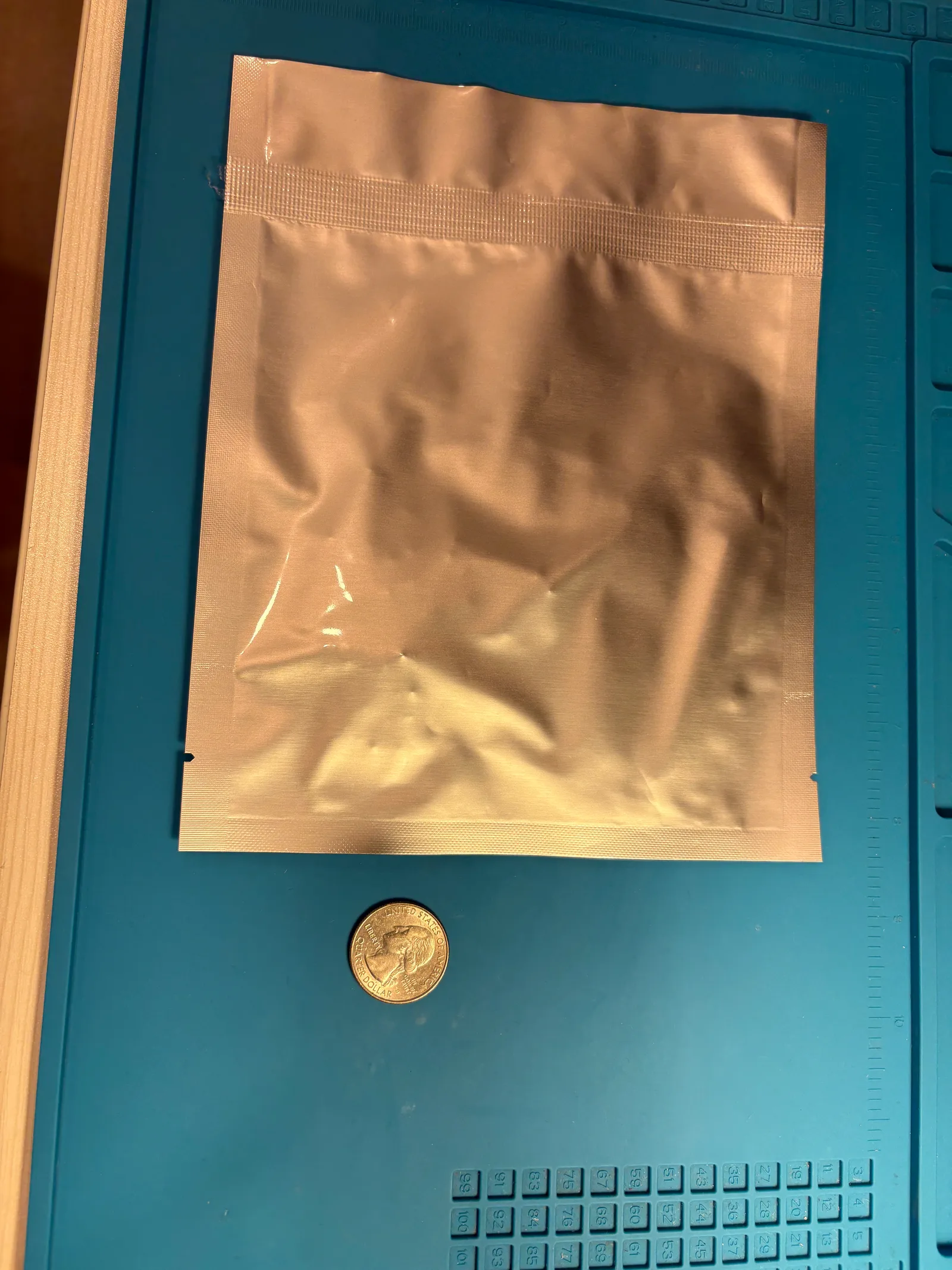
The LEDs arrived in a moisture sealed bag
which contained an anti-static bag
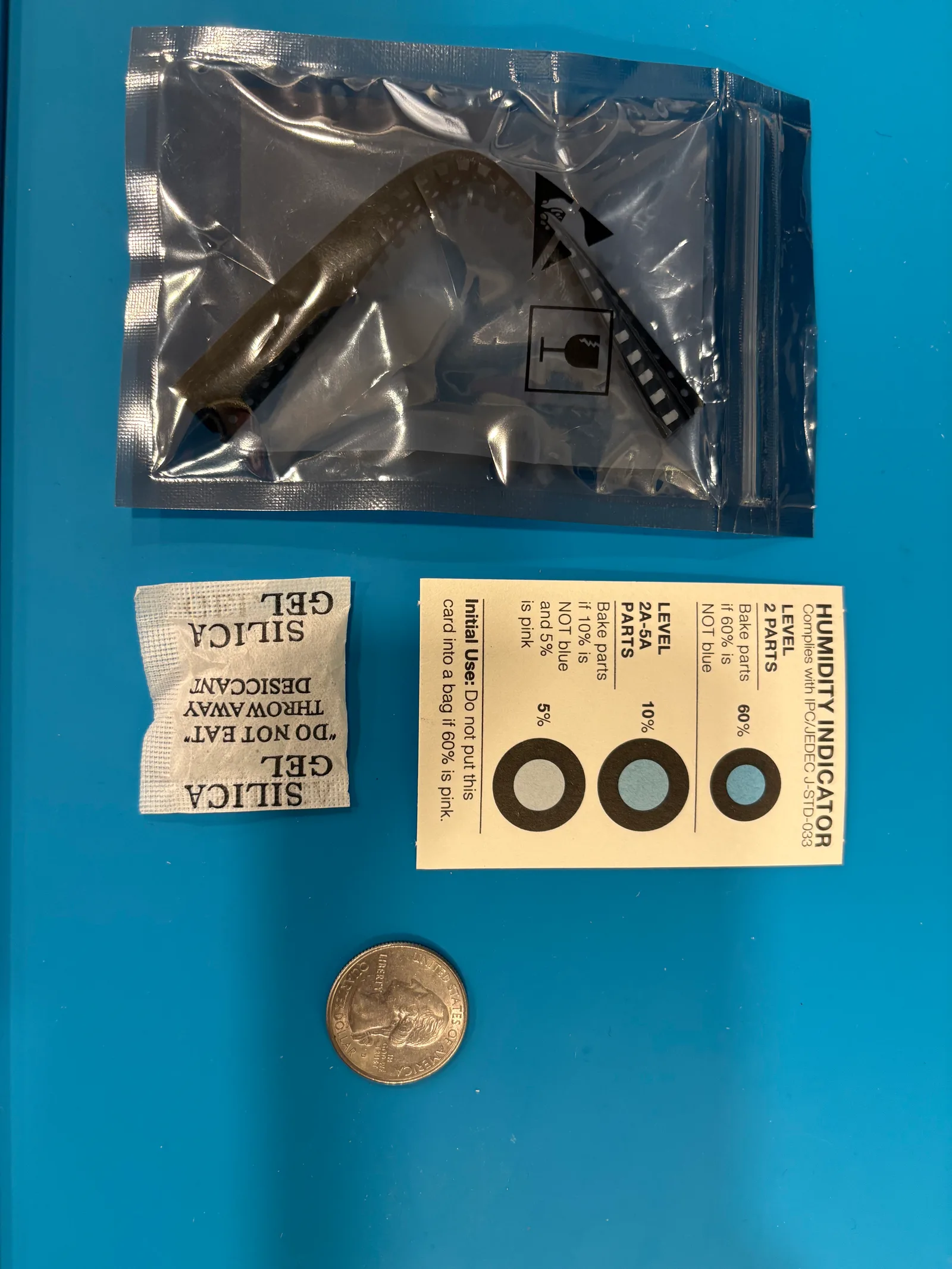
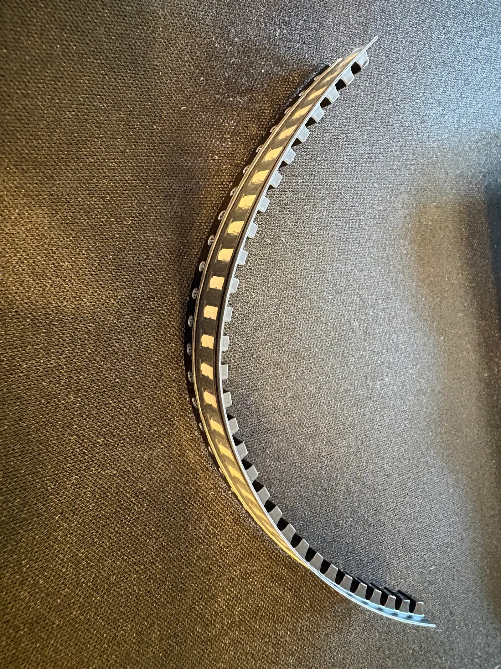
which contained the LEDs packed in a plastic strip.
Here's two loose LEDs:
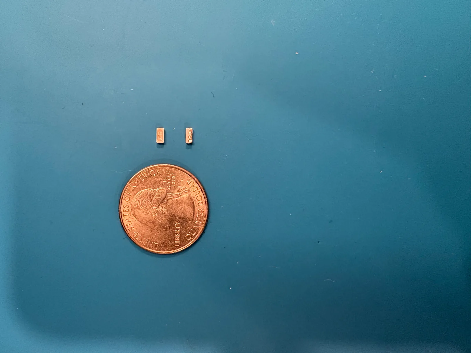
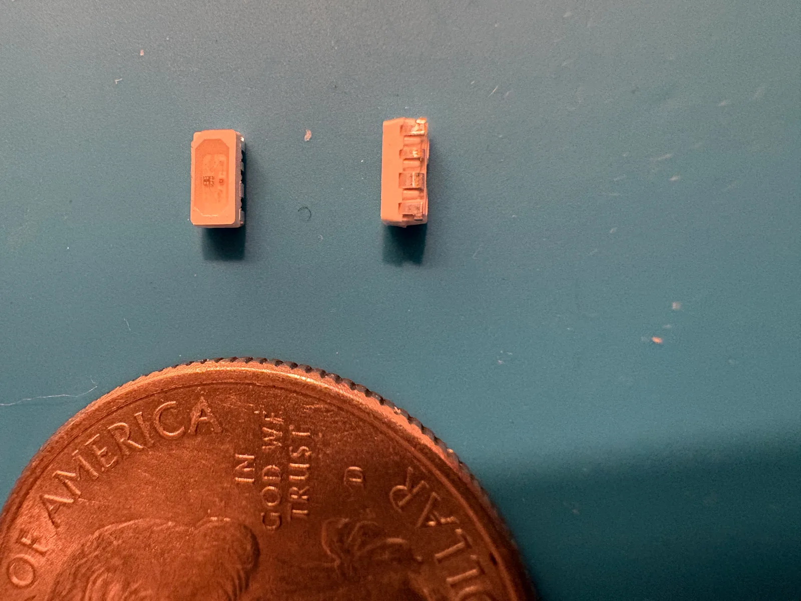
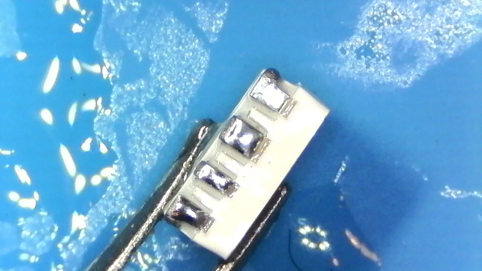
Those pads are very small.
The repair
Here is the process that worked for me.
I wet the pads on the LED by dragging the iron tip across them. It took a few tries to get the right amount of solder. Too much causes shorts. Too little and some of the pads aren't connected. I used Sn63 Pb37 solder, though a mix that melts at lower temperature may have worked better.
I cut the remaining ground trace pad off the board to reduce the risk of a short.
I placed the LED on the board using the other LEDs as reference. I then used a hot-air reflow gun to heat the whole LED until the solder melted and bonded to the vias. Around 10-15s with the gun set to 350 °C and the lowest airflow setting. It took several tries to get all four pads to work. Check continuity to the adjacent LEDs with a multimeter.
The temperature I used far exceeded the max in the datasheet (260 °C) so the LED enclosure melted a bit. But all three colors light fine, at least for now.
The LED is attached, but is holding on by just the vias. I added some hot-glue for structural support.
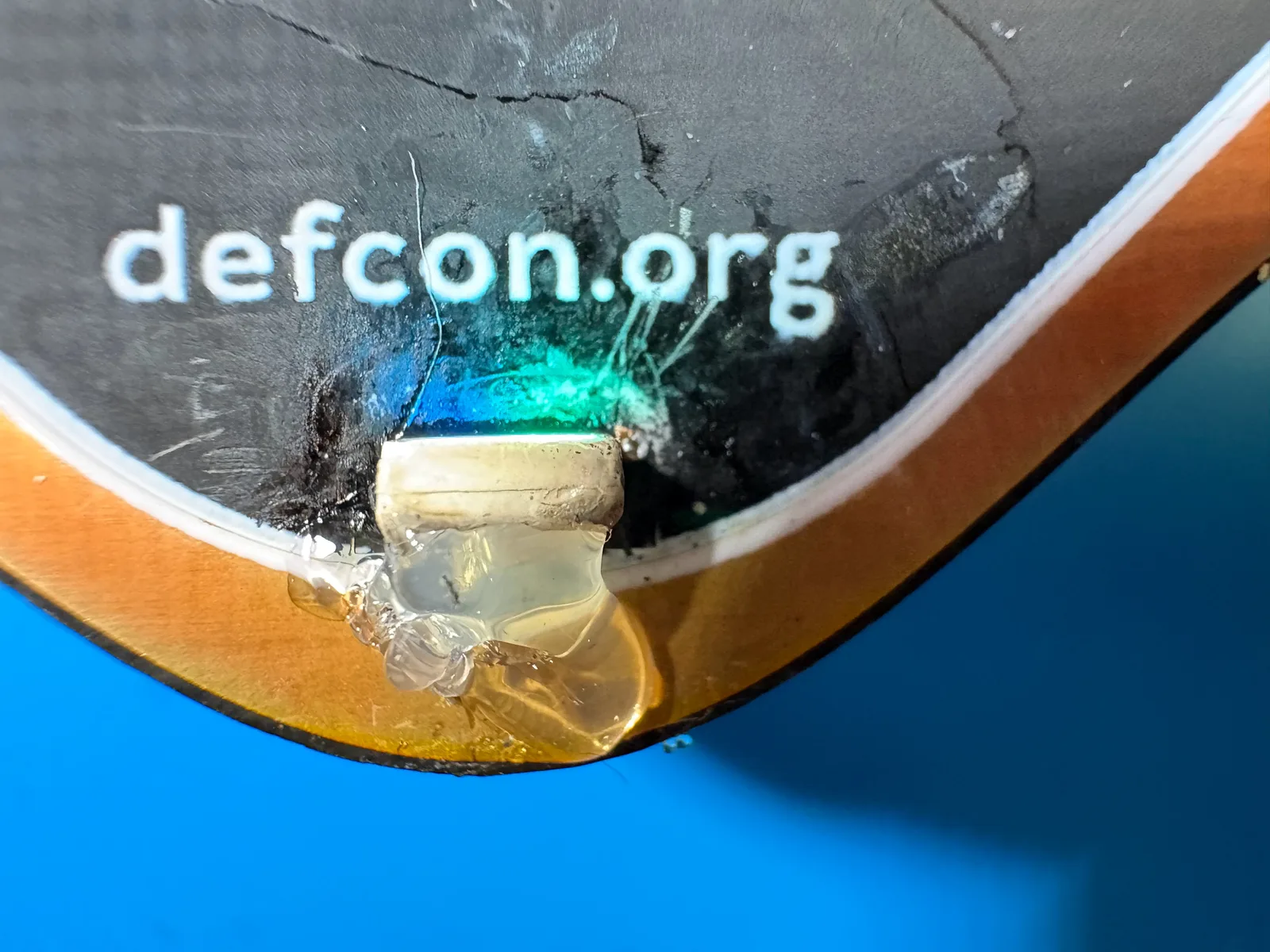
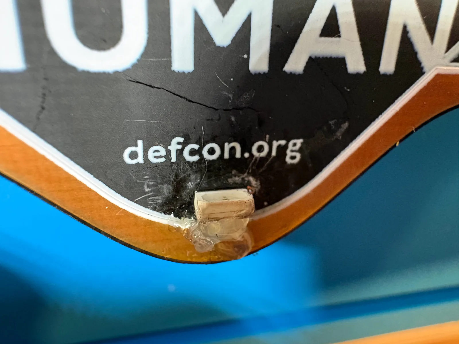
Here it is running. The replaced LED is the one at the bottom, below HUMAN.
A hack
The original failure mode is now unavailable. I have replaced it with several new ones. Pads are gone, but vias are a very poor substitute. A better fix might replace the pads or run tiny wires. Hot glue is not a real adhesive. Cooking the LED could easily make it fail early. Ideally use low-melt solder and stay within the part's spec. However, my fix might outlast the original factory install, which I'd consider a win.